Background mesh#
In this step, the background mesh is created.
For the background mesh a bounding box is generated. During this procedure the OpenFOAM utility blockMesh is used.
Note
Other more complex background meshes are allowed but are not covered in this case.
They can be generated with blockMesh or any other meshing utility.
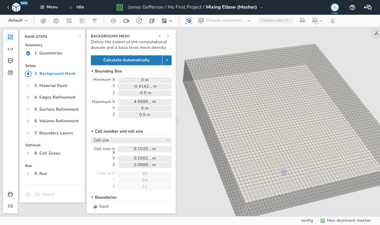
Bounding box#
The bounding box can be defined automatically or manually. It should surround all imported/created geometries of interest.
Automatically setting bounding box limits#
This option relies in the spatial limits of the input geometries. The geometries surfaces cn be regarded as a list of points in a three-dimensional space with coordinates \(\left(x_i, y_i, z_i \right)\) with \(i\) being the order of the geometric point. We can define a bounding box based on two points, \(B_{min}\) and \(B_{max}\), defined as:
\(B_{min}=(\min(x_i), \min(y_i), \min(z_i)),\)
\(B_{max}=(\max(x_i), \max(y_i), \max(z_i)).\)
These two points represent the diagonal of the bounding box and are computed automatically by just using the Calculate Automatically button. If the user wishes to increase the size of the auto-calculated domain size based on \(B_{min}\) and \(B_{max}\), there exist two levels of options for spacing both placed under the drop-down menu beside the Calculate Automatically button.
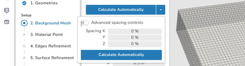
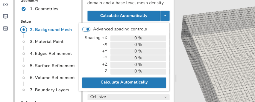
In the spacing options you can define the magnification percentages \(\left(\beta_x,\beta_y,\beta_z\right)\) for each direction.
For example if the size of the background mesh domain in the \(x\) direction is increased by \(10\%\),its size is computed from \(B_{min}\) and \(B_{max}\) in each of the positive and negative \(x\) directions. The same applies to the \(x\) and \(y\) direction. Negative values for \(\beta\) are not allowed.
Manually setting bounding box limits#
User can also manually enter the coordinates of the points \(B_{min}\) and \(B_{max}\).
Caution
Care should be taken not to exclude parts of the geometric surface of interest because these parts will also be excluded by the mesher.
Changing boundary types of the bounding box#
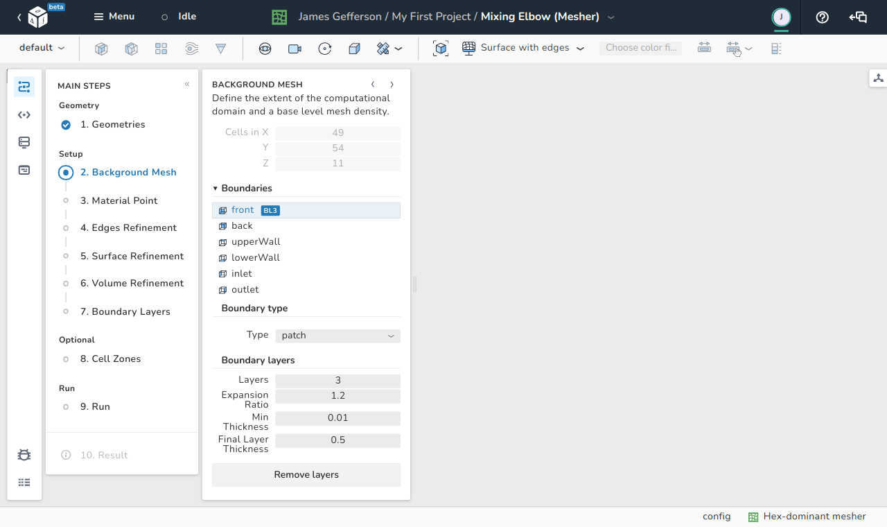
In this part, the boundaries of the background mesh are defined. First, selecting one of the boundaries enables the option to rename them to have helpful indicative names during the simulations. The default names of the six boundaries of the background mesh are:
- front
- back
- upperWall
- lowerWall
- inlet
- outlet
The default type is patch for all the boundaries. Beside the type, the user can establish layers on each boundary in the same sense of the boundary layers on a geometric surface. The function of these options can be summarized as:
- Layers: Indicates the number of layers built on top of this boundary.
- Expansion Ratio: Represents the ratio of the geometric series of the layer sizes. If for example the ratio is 1.2, then each layer thickness is 1.2 times its predecessor's thickness.
- Min Thickness: This entry provides the meshing utility with a minimum layer thickness to avoid too thin layers over the surface.
- Final Layer Thickness: This entry defines the thickness of the final layer of the boundary layer.
Finally, beside the name of each boundary, a logo specifying the number of layers is shown. In the above image, the logo BL3 is added as 3 layers are specified for this boundary. The Remove Layers button deactivates the creation of layers on this boundary.